FreePCB Build: MSP430F5310 Breakout Board from Dangerous Prototypes

Quite a while back, I got a FreePCB Coupon from Dangerous Prototypes. It took me a while (2 weeks to be precise ) to figure out what exactly what i might be able to build based on the limited inventory I possess. Finally, i found this gem in their FreePCB Drawer. It was a MSP430F5310 breakout board. I have been lately trying to learn to use MSP430. So, it would be a great pick. Also the IC can be sampled from TI and all other components were passives.

Plus it had quite a few other breakouts panelled together which maybe an SD Card breakout etc.

I went to the blog mentioned, to find out these were originally picked up from India 😀   World is a small place..But unfortunately coudn`t find the link to the git which i found later after a random search on DP.

This is the article and the comment by Boseji to his git repo for the project that was extremely useful in building it!

So, finally i ordered it and after a few weeks i received a mail(package) from Ian from dangerous prototypes in my mailbox.

DSC05341

It was a very beautiful PCB with a green solder mask, white silkscreen and all pads tinned. It seemed to be 1.6mm FR4.. Beauty!!

It was furnished by Seeedstudio`s Fusion PCB service. I then quickly sawed away the unwanted parts and filed the edges with a Dremel to extract my share out of the bounty!

DSC05470

In the meantime , i had already sampled F5310 from the estore now. This was probably the first( or maybe second) time i was to solder an SMD and the first time for a QFP Package. I looked up a few tutorials on youtube for drag soldering , but that didnt work for the first time.. 😦
So, i worked out a better trick i tinned the pads very finely to get some solder on it and then placed the IC, cleaned the tip,injected some liquid flux and applied some heat and pressure from my soldering iron and voila, all pads soldered correctly! Just to make everythings correctly done..i checked the continuity quite a few times .. I got a bit carried away and clicked a whole bunch of pictures! 😀

DSC05522

DSC05518

Now, came another trouble, NO SMD COMPONENTS FOUND !! The local dealers wont sell me small qty of caps or resistors! What am I gonna do with 5000 Reel and that too of the same value? (Although a bit later after completing the board somebody told me about another dealer selling them in quantities of 100 at a 10X cost) .  Battling the question for a few days i found out a neat trick to bend the through hole resistors to get them to fit on the pad, the same goes for the caps!
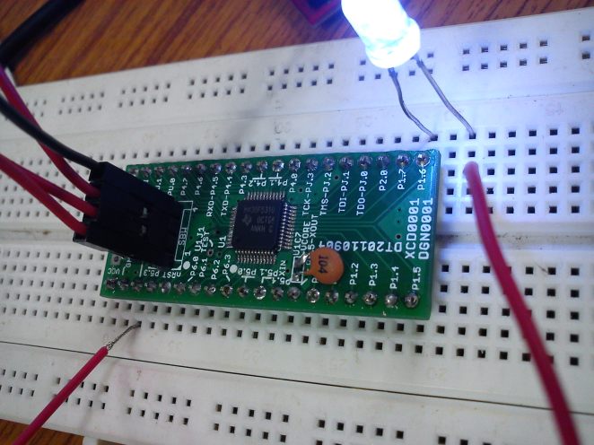
So, here is the completed board,

DSC05527

DSC05529

Some pads are vacant as they just had some caps in place.. i used some of higher values to compensate for them! 😀

DSC05618

Here is the Youtube video of the blink demo running on it! The board was programmed using SBW protocol using Launchpad as a SBW Programmer!

Thanks Dangerous Prototypes for sending this through.. It was a really nice experience building one!

Cheers,

Indian Tinker!

Tiano-MSP430 based TouchScreen Piano

Touchscreens..huh.. They are all around us..Phones ,tablets, phablets and now even laptops. Most of them have a capacitive touchscreen where the change in capacitance at a point is used to sense it and then perform the corresponding action. Capacitive ones are multi point sensing. They sense more than 2 points and hence we get those pinch to zoom features etc.

On the other hand , almost archaic version on touchscreen is the resistive version. That are pretty easy to interface with almost any microcontroller with an ADC. In this project i did over the weekend i tried to interface a touchscreen ( resistive one..) ,available at mobile repair shops in Delhi with a MSP430G2553 (Although MSP430G2231 would also do)  to make a piano.

Touchscreen setup

Pre-requisites: The touchscreen may not be easier to get. I got mine from a mobile repair shop in LR. It is a 4-wire Touchscreen, pretty common with horribly thin contacts that took a lot of patience to solder.There is a lot of literature available on Touchscreens on the internet. I found two app notes that were best. First one from Atmel , that explained the working of the touchsreen in a pretty clear way and one from TI that some what helped in the software part.

You must read the atmel one ( atleast the first few pgs to get how it works). Its essentially a resistive voltage divider. The value of the touch point is determined by the ADC value read.

formula

From the illustration above(borrowed from TI App Note). One can easily see how the co-ordinates are read. In order to find out, what wire on your touch sreen corresponds to X and Y meshes. You can use a multi-meter first to measure the resistance between pins ,usually the alternate pins belong to same axes. in my case it was X-,Y-,X+,Y+  then to differentiate between x and y , one probable method will be to power the touchscreen i.e. giving the drive voltage and then find out the voltage at any other terminal w.r.t. ground and see whether is changing horizontally or vertically in your reference plane.

CAUTION: Be careful about the current while powering the touchscreen externally!

After this coding part is pretty simple. For the algo refer to page no.7 on the TI App Note. If you plan to run your end application on a battery and you have hard-coded the co-ordinates and the Vdrive is sourced externally i suggest that you sample the Vdrive as well . If you are using  microcontroller pins to supply Vdrive then this can be neglected.

I have a desire to learn to play music but unfortunately due to my low patience levels , i have failed to keep up. 😀

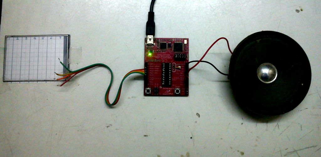
So, i made this Piano using the MSP430 Launchpad and a touchscreen along with a speaker. The code algo is pretty same as TI App Note Suggests and i encourage the reader to code it himself . Any difficulties can be discussed. It uses the tone library i posted earlier to generate the solfeggio.

Here is the shaky and horrible video i made:

Cheers! 😀

Reverse Engineering an Automobile Fuel Gauge using MSP430 Launchpad

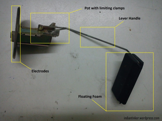
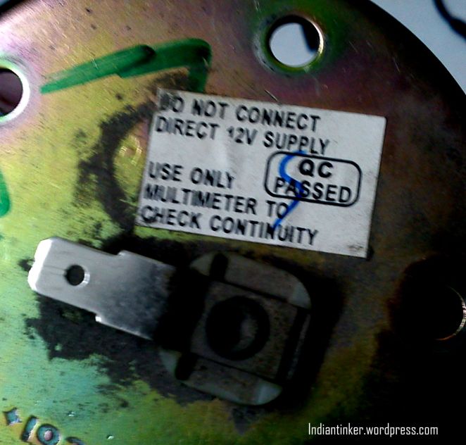
I have been keeping my hands off the blog for a while after the previous post.. I had exams at university. But in the meantime i had some time to get my car`s faulty petrol/gasoline Gauge Indicator Changed. I got the old one and as usual i tried to reverse engineer the gauge with all the simple tools i had. Technically, Its a ” Floating type Liquid Level Resistive Transducer’ (You can trust me on that..I am a student of Electrical Engineering 😀 ). So basically its a variable resistor much like the LDR or a Potentiometer. The one that i have is a pricol make for Maruti Suzuki Cars. You can have a look at the pictures below. DSC05612

DSC05610

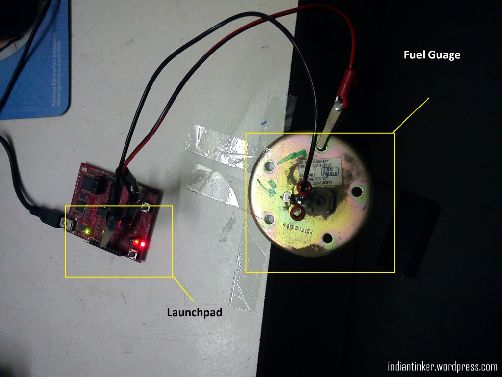
Using the TI MSP430 Launchpad i decided to sort of simulate how the Indicator would actually work in real situations. So i pulled up the ADC Pin on the MSP430G2231 using a 220 ohm resistor and connected the fuel gauge indicator as in the set-up picture you can see below.You can use any platform you like arduino,stellaris etc. all you need to do is read the ADC value and produce a corresponding brightness for the LED and when at a low level raise a low fuel alarm which in my case is the RED led. I used Launchpad as it has Two on-board LED`s while my arduino has only one ; additionally i was lazy enough not to wire another led to arduino 😛 .

DSC05614

On measuring the resistance across the fuel gauge i found that when at the lowest position it has a resistance of about 112 ohms and at the maximum it was about 7.2 ohms. On the sticker pasted on the top its mentioned-” Do not connect direct 12 volts”.Which is pretty obvious because since the resistance is low, the current will be pretty high.

12/112=0.1amps

but on full scale its about 12/7.2 ohms=1.67amps

This current is pretty high and will surely burn the coil.

So we now know why the sticker is there! 😀

The program simply blinks the red led when there is low fuel. Rest of the time the intensity of the Green LED is proportional to the amount of fuel thereby producing a variable DC voltage which can be sensed using a voltmeter quite similar to the one fitted in the car console.

TL;DR

Watch this video:

Thanks and Regards,

IndianTinker 😀

Texas Instruments India Analog Design Contest 2012-2013

Recently me and my friend partnered for TI ADC 2012-2013. We made a ‘multi nodal wireless instrumentation and Telemetry system for Solar Cars”. This was entirely based on Ti products and the same model can be extended to low cost plant monitoring systems also.

These are the Booster Packs for Launchpad we made in the process. The lower one contains all the required stuff  i.e. regulators and connections for driving heavy automobile loads..The upper one contains the sensors and an optional LCD just in case of monitoring the system dynamics.

DSC05412

You may have a look at this entry video we made!

Edit: We have won a consolation prize in the event 😀   ContestPost

Cheers and Regards,

Indian Tinker

😀

Tutorial: Using Crystal Pins as I/O on MSP430

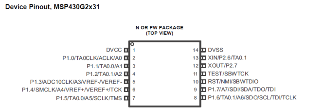
Sometimes we often face situations like lesser GPIO pins when working on “peripheral optimized” microcontrollers like MSP430 which offer a perfect balance of cost to feature ratio. The MSP430G2231 which comes with the older version of launchpad (v 1.4) has 8 I/O on Port1 and the datasheet also says that the crystal pins(XIN and XOUT) can be used as I/O with an interrupt capability but there was a lot of ambiguity on how to actually use these pins as I/O.

CrystalIOPIC1

Even the user`s guide which is very lucid and clear on all peripherals does not mention the way to use it. After failed searches over the web for the correct way to use them..I started experimenting with the launchpad to find it out.

I figured out that by default the pins for the crystal are initialized in the ” Reserved ” mode as mentioned in the user guide:
CrystalIOPIC2

Its just a simple job but it took me sometime to figure it out.. 😀
So, now all you need to do is clear the PxSEL2 bit and what you get in return is a generous gift of two extra I/O`s. This is “critically” useful while interfacing 7segs using standard multiplexing techniques .
The code is given here as follows:

/*
Using Crystal Pins as IO
Microcontroller: MSP430G2231
author: Rohit Gupta
Email:  rohit7gupta [at] gmail [dot] com
Date:   14/1/2013
Homepage:www.indiantinker.wordpress.com

Compiler: Code Composer Studio on Windows 7 64bit Machine
Copyright (C) <2013>  <Rohit Gupta>

This program is free software: you can redistribute it and/or modify
it under the terms of the GNU General Public License as published by
the Free Software Foundation, either version 3 of the License, or
(at your option) any later version.

This program is distributed in the hope that it will be useful,
but WITHOUT ANY WARRANTY; without even the implied warranty of
MERCHANTABILITY or FITNESS FOR A PARTICULAR PURPOSE.  See the
GNU General Public License for more details.

You should have received a copy of the GNU General Public License
along with this program.  If not, see <http://www.gnu.org/licenses/>.
*/


#include<msp430g2231.h>
void delay_ms(unsigned int ms )
{
      unsigned int i;
      for (i = 0; i<= ms; i++)
        __delay_cycles(1000); //Built-in function that suspends the execution for 1000 cycles
}
void main(void)
{
	WDTCTL = WDTPW + WDTHOLD; //Stop the watchdog..bow..boww
	P2SEL&=~(1<<7); //Clear the SEL bit to enable use as a IO pin
    
	P2DIR|=(1<<7); //Output at pin2.7
        P2OUT&=~(1<<7); //Turn On LED on Pin 2.7
	while(1)
	{
		P2OUT|=(1<<7);
		delay_ms(500);
		P2OUT&=~(1<<7);
		delay_ms(500);
	}


}

They youtube video is being uploaded to see this in action.

So, Go ahead and grab those extra I/O`s being left unused :D.

Happy New Year 2013!

Cheers,
Indian Tinker

Tutorial: Using the Internal Temperature Sensor on a MSP430

The value line series (g series) chips that come with the MSP430 Launchpad are pretty cool and has almost all the required peripherals to work with..The best on is ( for those with the newer version v1.5 or later, that comes with pre-soldered Male headers ) MSP430G2553, It has pretty much everything to get you started. Since, I was a little curious i bought the MSP430 launchpad quite a while back..Mine came with a g2231 and g2211..Of which G2231 is the one that has an ADC. The MSP430 boasts of an internal temperature sensor which is probably new to me who has worked earlier on AVR. So, I went on and tested the ” <Accuracy>”  of the sensor.

For you to proceed you need to have this (user`s guide) and refer the pages 559-564.

post1

So setting the bits in the INCHx to 0b1010 (i.e 10 in decimal) the MSP430 allows us to use its internal temperature sensor.

We have chosen the reference voltage to be 1.5V in order to have an ADC Value that is more or less immune to the Voltage Fluctuations.

The code is as follows:

#include<msp430g2231.h>
void tempInit()
{
	ADC10CTL0=SREF_1 + REFON + ADC10ON + ADC10SHT_3 ; //1.5V ref,Ref on,64 clocks for sample
	ADC10CTL1=INCH_10+ ADC10DIV_3; //temp sensor is at 10 and clock/4
}
int tempOut()
{
	int t=0;
	__delay_cycles(1000);              //wait 4 ref to settle
	ADC10CTL0 |= ENC + ADC10SC;      //enable conversion and start conversion
	while(ADC10CTL1 & BUSY);         //wait..i am converting..pum..pum..
	t=ADC10MEM;                       //store val in t
	ADC10CTL0&=~ENC;                     //disable adc conv
	return(int) ((t * 27069L - 18169625L) >> 16); //convert and pass
}
void main(void)
{   volatile int temp;    //initialise
	WDTCTL = WDTPW + WDTHOLD; //stop..bow..boww
	temp=0;
	tempInit();//initialise adc
	while(1)
	{
		__delay_cycles(500); //wait and set break point
		temp=tempOut();           //read temp
		__delay_cycles(500);  //wait and set breakpoint

	}
}

Code is under this licence .  😀

So, when you flash this code using CCS the breakpoints need to be set(Not compulsory et`all). What breakpoints really do is that it stops the program there and allows you to see the value of the watch expression and then when you press the pause/play button again..it will run until the next breakpoint..Its a pretty cool feature..and many use it to analyse code behavior.

This is how you set a breakpoint in the CCS-Edit window:

post2

Just click on the bar next to the line number bar..(Currently highlighted in blue).

These are the results you get by setting the “Watch Expression” to the Temp variable..

post3

The temperature it reads is 23 Degrees Celsius..while my room temperature measured by a standard thermometer is  20 Degrees. which is a relative error of 15%. So, scientifically that`s not accurate..but i dont think that is what it is designed for..I think it is designed for just to give an “Idea” of what the temperature is about..So we can see if we are getting colder or hotter.

The code is pretty well commented and i find it self-explanatory..But still if you have any query ..I am just a “Comment” away!

You can also find the complete CCS project in this repo on github!

Cheers and Greetings!

Indian Tinker!

TI MSP430 Dice( and other experiments)

7 Segmented Displays are pretty low tech and have been around for quite a while.They have a lot of wiring clutter with them..But still they are by far the most easiest(and cheapest) way to give out a (alpha)numerical output..I had interfaced 7segs with MSP430 a while back directly but owing to the low current capabilities of MSP430 the display wasn`t very good and clear . We were recently ‘taught’ about the BCD-7 segmented display in our semester..So i thought about interfacing the 7 segmented with the CD4511..This will save some precious pins and plus drive the 7 seg directly. The CD4511 IC can run from 3V Supply..So no power supply issues and the logic high(input) is about 2V which is also apt as on MSP430 we have this about 3.3V.

The datasheet is available  here

The only thing that was bad was the wiring clutter  has increased and there were (as always) a few loose connections.After a few minutes,I was up and running with the display.

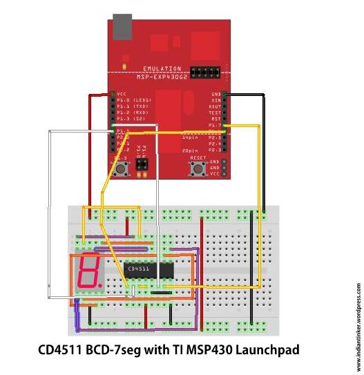
The Fritzing Schematic is given below:

cd4511

Do everything according to the picture above for the code to run. If the Schematic is not clear..then refer to datasheet linked above.Everything has been done according to it..The LT(bar) and BI(bar) have been connected to +VCC and LE to ground.The display is powered from the ‘board’.

The connections (from the MSP430 end to CD4511) are:

P1.4 -D

P1.5-C

P1.6-B

P1.7-A

#define D BIT4
#define S BIT5
#define B BIT6
#define A BIT7

The code to drive the CD4511 “According” to the above config is:

void CD4511(int numb)
{
switch(numb){
				case 0:P1OUT&=~(B+A+S+D);
				break;
				case 1:P1OUT|=(A);
				       P1OUT&=~(B+S+D);
                break;
				case 2:P1OUT|=(B);
				       P1OUT&=~(A+S+D);
                break;
				case 3:P1OUT|=(A+B);
				       P1OUT&=~(S+D);
                break;
				case 4:P1OUT|=(S);
				       P1OUT&=~(A+D+B);
                break;
				case 5:P1OUT|=(A+S);
				       P1OUT&=~(B+D);
                break;
				case 6:P1OUT|=(S+B);
				       P1OUT&=~(A+D);
                break;
				case 7:P1OUT|=(S+B+A);
				       P1OUT&=~(D);
                break;
				case 8:P1OUT|=(D);
				       P1OUT&=~(B+S+A);
                break;
				case 9:P1OUT|=(A+D);
				       P1OUT&=~(B+S);
                break;
				default:P1OUT&=~(B+A+S+D);
				break;
}
}

Just to clarify :The code uses ‘S’ instead of ‘C’ because C was being used as an internal macro in the header file!

The video is down here..It first shows the simple counter..then the push to change count and then the Dice.
To get the complete source code..you can comment below..The comments are moderated so you email will not be leaked.
Thanks for passing by!
🙂
#Sorry for the bad cam! 😛

Tone Library for MSP430

We all like things that sound..About a month ago, A friend of mine asked me to make her a musical card..which she wanted to gift to a friend who is a guitarist( She herself knows Piano). She wanted to dedicate the song she made to her..So, she gave me the tones and durations of each tone..So that i can code it and play the tune..Since, Its all monotonic ..so it didnt felt like a piano..but the tone was clear.

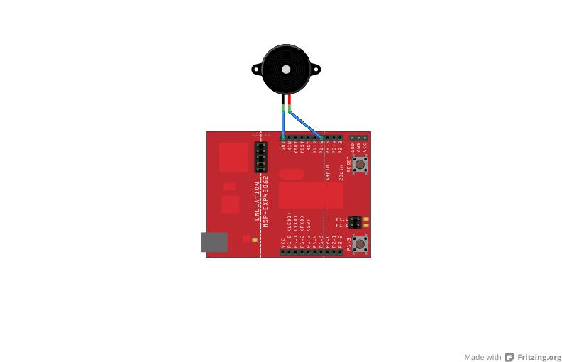
Connection Diagram!

The one I gave her had a MSP430g2211. Just to test the tune settings earlier, I had played Happy Birthday..By borrowing the notes from a website.

The notes were:

c c d c f e
c c d c g f
c c highc a bflat g
a a bflat f g f

Earlier.. I made it using the traditional delay way. But later, I figured out how to do it using the Hardware PWM. The trick is that every note has a particular frequency.If we set the channel for  half the duration and then reset it for the next half. We get a PWM of 50% Duty cycle at the given frequency..Taddaa..Thats all..instead of generating  a sine wave, we are making a square wave.

The exact tested frequency for the notes are available here !

This is the function i coded:

void tone(int tone,int duration)  //Tone macro and duration in millisecs.Play other frq simply divide it (smclk/notef) to get the counter period and feed it into the function
{   int i;
	for(i=0;i<duration;i++)
	{ CCR0=tone;       //Tone length
	  CCR1=tone/2;     //Half Tone ON and Half tone OFF i.e 50% duty!
	  _delay_cycles(1000);
	}
}

Now another problem ..was that how to stop the Tone..since it(tone generation) is not done using software bit-banging ..I can`t set the Output to Zero just by clearing the bit..but we can definitely make the period zero. This is how i coded the notone function:

void notone(int i)        //To stop the tone can`t use delay_ms as its a hardware PWM not software!
{

	CCR0=0; //make main period zero..it doesnt work when you set CCR1 to zero because it will always set-reset at zero.
	delay_ms(i);
}

Now we need a toneInit() Function..to initialize the PWM:

void toneInit() //Initialise The Timers
{

CCTL1 = OUTMOD_7; // CCR1 reset/set

TACTL = TASSEL_2 + MC_1; // SMCLK, up mode
}

Hope You all like it. If anyone wants the Complete Code..He/She can comment with the email id. The comments are moderated.So don`t worry about your mail ids going public. 🙂
Here`s the video..Wish a geek Happy Birthday!

I know the camera is bad! The tone can be tinkered/tuned a bit..I leave to the reader.. 😛

UPDATE: 30th Nov`12

Pingback: Littlebirdelectronics.com

Update 6th Dec:

You can fork the code from github here.

MSP430 Based Touch Interaction

I recently ‘got’ a Capacitive Booster Pack from Ti in a competition.

I decided to play some games involving simple controls with it.It is a great little booster pack which lets you do cool stuff like gesture recognition ( Touch gestures..like rotate,slide etc.). As an initial experiment i decided to play Poto and Cabenga  . It is a funny little time killing game..where all you need to do it to just press the “SPACE-BAR” ..Cool enough..for lazy geeks(ahemm like me)..

I decided to do it using the

TI MSP430 Launchpad + Capacitive Booster Pack+ Some Windows Shell Scripting

This is what i got:

Just wave the hand above it to get it out of the LPM(Low Power Mode)..this activates the script and then until it sleeps..the script is active..

Hope you like it..I will post the scripts soon..So stay tuned!