EventReport: Renesas GR Sakura Competition India

Today, I got a chance to present my project at the finals of the GR-Sakura Design Challenge in New Delhi at Radisson Blu-Dwarka. Although i did`nt win ( 😦 ) But, It was a great experience to be there and meet new fellows. I clicked some pictures of interesting projects and prototyping ways. It was great to see people use 3D printed motor mounts and extensive use of android phones in projects. One out almost every 5 projects had an android assisted interface.

The Radisson Blu Hotel, Dwarka

My Project


My Setup 😀

First one to reach!


The Stage!

Yet to start!

The Registration Desk

Exclusive Preview to Kurumi Board

Preview To Kurumi Board

Automatic Diesel Generator Control

Automatic Diesel Generator Control by Power Grid

Train collision avoidance system

A Train accident prevention system with sub-metre accuracy using GSM-GPS-GLONASS-WAD made by very senior person with about two decades of experience in designing safety systems. He also won a prize !

Farm Automation based huge project

A huge farm automation project with almost everything LabView+Android+Sakura+Servo+Panel Tracking.. and the list goes on!

IIT Bhubaneshwar used 3D printed mounts

Another Great project from IIT,Bhubaneshwar.It studies the control requirements for designing a Uni-cycle.These guys have a huge stratasys 3D printer at their college which they call RPM-Rapid Prototyping Machine. They built the mounts for the motor and pulleys using solid works and later printed them.

PLC based on Sakura

A PLC based on Sakura Board

Vibration Analysis

Another interesting project which uses accelerometer and Temperature sensors to determine whether a rotary machine follows the ISO standards!

Project Idea

I met a really interesting person at the event. Butani Sir is from Rajkot and has a very good knowledge of topics ranging from Microcontrollers ( you name any! ),Dev Boards, Aero-modelling,Graphics and Hands-On in general. He is a professor at a college in Rajkot and has a Btech,Mtech in ECE.This is his idea of a final project would look like! Cool Sketching 😀

Butani Sir and his project

Butani Sir while packing up (He too has a Chronos)!

Nice Way of Prototyping

How he did the board was real cool. Using his exp. from aero-modelling he made it almost like a shield and glued dangling components. Tip for ppl who prefer the perfboard

Intense Moments

Judging

Judging in Process

The Entire Setup for demonstration

Prize Distribution

The prize distribution

To view the entire set go here.

It was a great event.This was their first edition. If they ever plan to scale it up, they can see how TI does it in India.

Looking forward to hearing from you all!

Unboxing Sunday: Renesas GR-Sakura Board

I recently got a cool new development board by participating in a competition by India`s premier Electronics Magazine- EFY or Electronics For You. The board is a Renesas Rx-63N microcontroller based developement board that has been coloured quite interestingly. It has a ‘PINK’ solder mask. Thats quite rare color for the solder mask. The word ‘Sakura’ means Cherry Blossom which is probably pink in color and hence the justification of pinkish tone of the board.

GR Sakura Board Box

GR Sakura Board Box

Delivered/Facilitated/Distributed by Element14

Delivered/Facilitated/Distributed by Element14

So Lets not waste any time and see what we have inside this tiny little package!

DSC06244

DSC06246

Opened! 🙂

DSC06247

The first thing you see is the getting started card with text in both English and Japanese. The box is about 2.8 X 2.4 inches and nicely done.

Here`s what the getting started slip has to say!

Plug and Play!

Plug and Play!

Hmm,Pretty straight forward! (will cover the entire process in the next post) It has been made by Wakamatsu Tsusho Co. Ltd and yeah.. Made in Japan! 😀

Here comes the angel!

Here comes the angel!

We can see the pin map and the board has an Arduino form factor. Behind we have the SakuraBoard in a bluish bag, probably ESD Proof. Some pins are 5V tolerant and are indicated in white color.

Box Contents!

Box Contents!

We  have a USB host connector for our USB needs. It hasn`t been soldered as that would make the board uneven from the bottom and hence, difficult to pack!

Here`s what the USB connector bag has to say:

DSC06259

Now lets unwrap the blue bag and meet our new Sakura Board!

Ah! Beauty..

Ah! Beauty..

DSC06253

RX63N uC @96Mhz

The ammo on board is a 32bit  RX63N 100-pin (R5F563NBDDFP) micro-controller running at 96Mhz. It has :

  1. 1 Mb Flash
  2. 128Kb RAM
  3. Tons of communication interfaces like: USB (host/function), Ether-MAC, I2C, SPI, CAN, IEBus
  4. 16 bit and 8 bit Timers and a separate WDT
  5. 12/10 bit ADC with DMA(Direct memory Access) [what it means is that data can be fetched easily from the ADC]

This was what the massive guy has inside it.

Top View:  DC Jack (5V only) USB for flashing Ethernet for communication LEDs,Regulator and Rx63N all in an arduino-like form factor

Top View:DC Jack (5V only), USB for flashing, Ethernet for communication, LEDs,Regulator and Rx63N all in an arduino-like form factor

Another View!

Another View!

Bottom View: SD Card for data storage,Un-populated XBee Connectors and tons of solder bridges to customize!

Bottom View:
SD Card for data storage,Un-populated XBee and USB Connectors and tons of solder bridges to customize!

This is probably the prettiest board i have seen.The pads,holes and vias are done very beautifully in ENIG to make them last long. There are mounting holes at same spots as Arduino Duemolive. The R5F563NBDDFP controller is in the LQFP form and probably machine soldered.

On board we have tons of features and the best part is that most of the board is Arduino Compatible not only in Hardware and well as software, this means you can use Arduino type IDE for Sakura Board too, better its web based ( will talk about it in  the next post) and most of the arduino shields are compatible. Thats the WoW Factor!

Lets see what the board real estate looks like:

▶USB function pins (mini-B): Download by USB mass storage (write)

//Means you can just compile code and drag and drop the .bin file into the device when it enumerates on the USB as a Mass Storage, Voila programming Done!

▶EtherNet (RJ45) pins : LAN such as Web server and remote download available

//On Board Ethernet connector and ability to work as a server and client ( #IoT guys will love it)
▶ USB host pins (A): applicable to Android-ADB-ADK

//On Board USB host.. WoW.. You ‘might’ be able to connect you keyboard,mouse and other USB devices.
▶ MicroSD jacket: possible to share data with PC

//There is an MicroSD card which can be used to log data and can be used to run music files etc.
▶ XBee ready pins: mount XBee module for wireless remote download

//There are unsoldered XBee Pads to connect your own XBee.
▶4 User LEDs and 1 User Switch..

That`s equivalent to an Arduino+Ethernet shield+SD cardAdapter+XBee Adapter+USB Host Shield.

On the whole, Its a pretty nice board and has tons of features meant for a beginner and advance users.They are several domains where it can be used, be it data logging, SCADA Applications,Remote Monitoring, IoT,Music Playback,and lots and lots of projects. The possibilities are huge! 🙂

If you need more information about the board, you can see this.

Hope you like the unboxing post. If you want me to try anything on this or if u have any questions, feel free to comment. If you made a dev board/shield and want it to be un-boxed/reviewed you can contact me here as well.

Stay tuned to see what happens when we play around with the web IDE for the board.

Till then,

さようなら(Sayōnara)(Bye in Japanese)

IndianTinker

Travelogue: Bangalore

Bangalore! Bangalore!!Bangalore!!! . Twice i have missed chances to go there.. The last missed chance was when i had invested a full weekend in planning out the probable travel outings after my presentation ends.. But due to unforeseen reasons.. I missed that opportunity.
Being a an Engineering Student and that too in the Electrical Engineering School , one never gets time to visit places too often ( Thing only an Engineer can understand ).

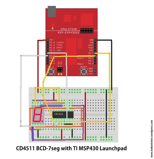
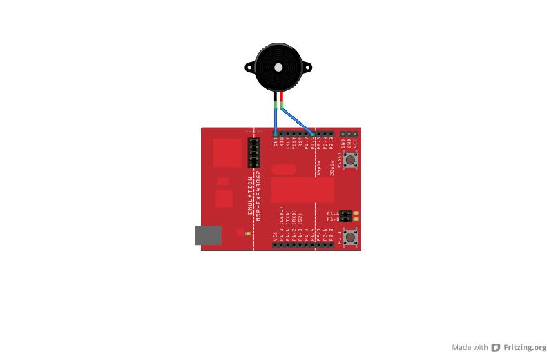
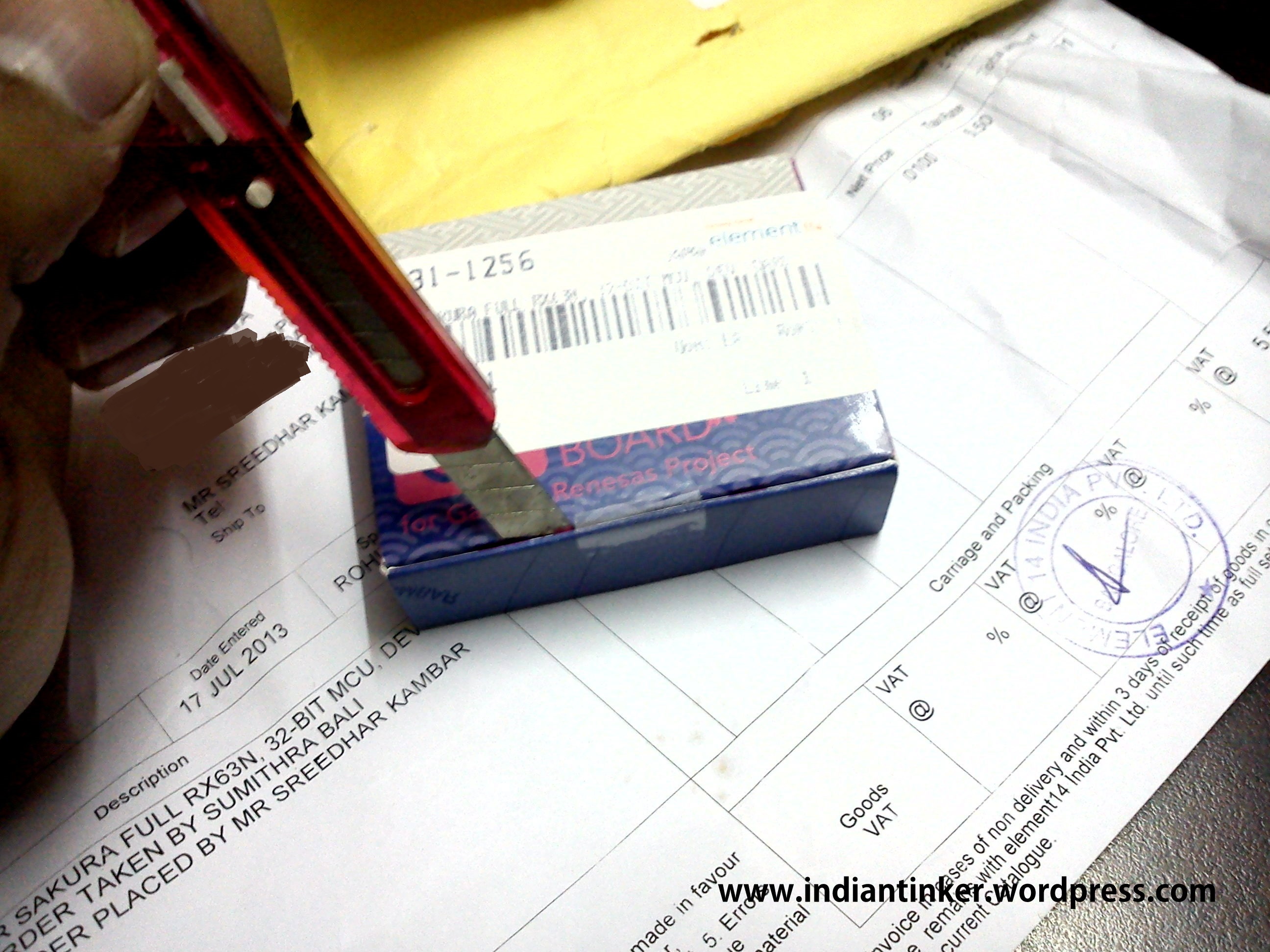
Long story short, I and my friend [Jaspreet] had made a project for TI-ADC 2012-2013 which ultimately got selected as ‘Consolation Prize Winner’. You can see the project video that we submitted  here . Basically it was  initially developed to log the data from our solar car and display it on the GUI wirelessly. Not only that we can switch many loads inside the cars like fans and lights but also we can monitor and control everything except the driver! We scaled up the project into a multi-nodal sensor system. The use of it is that we now don`t need to wire these units physically. The GUI does that entirely!

Micro-Nodes!

Micro-Nodes!

As consolation prize winners we had to present the paper at TIIEC-2013  and demonstrate the project at NIMHANS Convention Centre,Bangalore! At about the same time, another college team of [Shashank a.k.a Shank] and [RohitKrSingh a.k.a RKS], our juniors also made it to the Consolation stage with their Autonomous Ship Navigation System. It was great!! Now we all had to reach bangalore. The possible ways was by train or air! Train took a hell lot of time ( almost 2 days) and plane took just 2 hours. So we booked Air Tickets and We were soon on board Spicejet SG-211 !

All the participants will be grateful to TI as they had arranged accommodation for two in an awesome IBIS Hotel,Hosur Road ,  All meals, all travel and were even reimbursing us train tickets.. In the mean time ,since we had planned to visit and roam around in Bangalore and maybe visit Mysore we need accommodation for an extra 2 days.. Since we wont be staying in the hotel after the conference we needed some alternative place.. I ringed some relative and cousins in Bangalore and finally got us an accommodation for the next 2 days! I also made some city roaming plans in my little diary. I had heard that Public Transport connectivity is pretty good in Bangalore and one should refrain from taking the “AUTOS” . So , i noted all the major route and at least 3 alternative routes with bus numbers in case Google Maps ditched me! ( more on this later)

Sambhar Dosa- Not like the one we get here  in Delhi.Chutney and Sambhar served in equal qty.

Sambhar Dosa- Not like the one we get here in Delhi.Chutney and Sambhar served in equal qty.

Conference was great! We talked with a lot of like minded people from across our country and made new friends , learned some “Marathi” from the team we shared our booth with. Their description of the marathi songs we heard in some TV shows was enlightening !

It was the best exhibition i had attended and the best part was that our booth was the first of all, nearest to the gate. So , everyone would first come to our booth. [Jaspreet] did all the explaining most of the time. I was mostly roaming here and there, asking others exhibitors about their stuff ( Courtesy: Restlessness ).
I would be great to bring the fact that the Conference was inaugurated with an electronic lamp which is a project i was involved in.You can read about it here!

In between the conference after the day got over, i had to make a quick run to my aunt and the case was same for [RKS]. Apparently the route was pretty much the same. We had planned that all four of us will go, but that did`nt panned out . So, only two of us were going at their respective aunts. We walked to the Bomanahalli bus stand waited for like 40 mins. It was 9pm and none of the buses google said i could get, were coming.. Further, the place where my aunt stayed was kadubesanalli. I repeatedly kept saying it to the drivers/conductors and they all made faces like ” What the hell?? Is that a place , in around here? “.I found out i was pronouncing it very badly. Finally at 9:15 pm a bus came and a passenger said that go to the “Silk Board” and catch the bus. No bus goes directly from here.

We went to silk board and got the bus!
MISSION ACCOMPLISHED! The buses were great, very clean and with an air conditioner that was really effective! Reaching at my aunts place was not difficult after that. We returned at about 12 that night and crashed on the bed to go to the conference the next day!
I presented my first paper and then the next day was the Awards night!
Now, we had planned to roam around for the next two days! The IBIS Hotel offered us extended luggage vault this saved us a lot of miles else we would have to run to my brother about 20km away and that would cost us quite a part of the day.

As suggested, we took the One Day AC bus Pass ( Which i have secure in my ‘Ticket Collection’ ). As planned we would go to Banerghatta Park to watch some animals, then go to a couple ( which ultimately came down to one! ) museums. It was Saturday and roads to park was packed! The AC bus driver was playing local songs in Kannada ( i guess). The other passengers were enjoying it.. It was alien to me but i enjoyed the tune..
The bus conductor dropped us about 1.5km before the entrance of the park. I still don`t know why as the bus was there at the park when we reached. As we walked towards the entrance, we saw a group of “Art Of Living” volunteers on a cleaning mission, we shopped some drinks and local “namkeens” (which i am really fond of  tasting where ever i go) and at last reached the gate. Then, i turns out there are several options and ways to browse the park, we went with the most common one that is normal bus with cage like windows! If somebody happens to have been to Borivali National Park, the bus is pretty much the same! But the catch is that you have to occupy the seats in order of your entry to the bus and they are hell strict about  it.The Park is very well maintained and its not allowed to take any plastic stuff inside the park and the guard on the gate packed all the “namkeens” i had bought into separate paper bags!

Phew! We happened to be at the last one and we got the back seat and also there were lesser people so, we could choose, Right or Left??
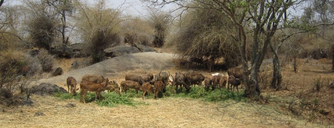
We ended up on the Left Side ( which was an awful choice as it turns out later ). The bus started, everybody got their shooters out . There are separate areas( bigger than those as in Borivali National Park ) for lions, tigers,bears, deers and elephants! The bus driver would stop at every place from where we could see any animal. This time we were in the cage and animals were in open. You can check out the pictures below and have a look at all the animals we saw. The bad thing happened on that particular day all the animals choose to come on the right side and we could hardly see then with all the people busy finding their niche in those 7 windows of the bus !  :/ . But thankfully [jaspreet] and [rks] chose the right side and they could click some pics which we rejoiced later!It was pretty hot that day, most of the animals were either in water or near water .
IMG_0681 IMG_0684 IMG_0713 IMG_0707
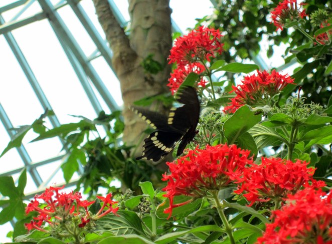
After the bus ride got over, we were left like in the middle of nowhere , A walk with the other people on the bus, ended up at the ButterFly park! It is a good place to visit and has a lot of nasty butterflies roaming inside the specially prepared bio-dome for them which creates the right amount of humidity for them to survive. There is also a museum about the butterflies which we quickly breezed through. We saw a lot of people bringing macro lens clad DSLR to click those tiny restless butterflies. Wonder how they (butterflies ) felt about the photo session (Random Thought !) 😀

Here are some we manage to catch in our CMOS-CCD!

IMG_0733 IMG_0738 IMG_0754

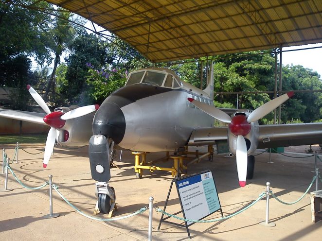
Having spent the day, in such a wonderful way was just great! To make it better, we wanted to go it HAL Museum which was pretty far. So, we boarded the Bus , which dropped us at Richmond and then we boarded another bus to HAL Museum. The stomach was ringing hunger bells but it can be ignored for a while as the museum entry closed at 5pm and it was already 4pm. We had to hurry! Fortunately the bus came in about a minute and we were on the way to the HAL Museum. But this time again, even after mentioning to the conductor that we needed to go to the “MUSEUM”. He dropped us 2.5km before. With the time not on our side and no bus stop near we had to walk..walk..walk..walk. During, the walk we saw some great labs (from the outside ) like Shape Memory Alloy Lab and Metal Workshops also. Being students of engineering the very sight of “Textbook” words written  on laboratory doors was pretty spell-bounding and assuring that what we are studying is not fiction.

So, we reached the Museum all drenched in sweat and thankfully the doors were open. We got in.. We saw a PSLV Heat shield (used/recovered/prototype ) in which the satellites are protected during the launch!

Heat Shield Inside!

Heat Shield Inside!

There are several real models of planes used in Indian Airforce and they are pretty well presented. Apart from that there is a whole museum of circularly arranged chambers which show Indian History as far as Aeronautics is concerned. We were blessed by the presence of [RKS] who in my eyes is the mobile wikipedia of Aeronautics. The moment he say a name plate which may be of an engine , ejection system or the plane.. He would tell us about the history and specifications of the engine and all such details which none of the display boards mentioned. It is a great place for someone who is interested in seeing planes.

DSC05717 DSC05724

We spent close to an hour in the museum and then we were back at Mc`Donald`s for feasting! We then boarded the bus back to IBIS Hotel (actually a couple of buses) to get our luggage and move to JNCASR,Jakkur where my brother was waiting for me!

Ah! What a day spent after a wonderful conference!

We had plans for Mysore the next day! Catch it in the next edition i.e Travelogue: Mysore!

Stay Tuned!

Tiano-MSP430 based TouchScreen Piano

Touchscreens..huh.. They are all around us..Phones ,tablets, phablets and now even laptops. Most of them have a capacitive touchscreen where the change in capacitance at a point is used to sense it and then perform the corresponding action. Capacitive ones are multi point sensing. They sense more than 2 points and hence we get those pinch to zoom features etc.

On the other hand , almost archaic version on touchscreen is the resistive version. That are pretty easy to interface with almost any microcontroller with an ADC. In this project i did over the weekend i tried to interface a touchscreen ( resistive one..) ,available at mobile repair shops in Delhi with a MSP430G2553 (Although MSP430G2231 would also do)  to make a piano.

Touchscreen setup

Pre-requisites: The touchscreen may not be easier to get. I got mine from a mobile repair shop in LR. It is a 4-wire Touchscreen, pretty common with horribly thin contacts that took a lot of patience to solder.There is a lot of literature available on Touchscreens on the internet. I found two app notes that were best. First one from Atmel , that explained the working of the touchsreen in a pretty clear way and one from TI that some what helped in the software part.

You must read the atmel one ( atleast the first few pgs to get how it works). Its essentially a resistive voltage divider. The value of the touch point is determined by the ADC value read.

formula

From the illustration above(borrowed from TI App Note). One can easily see how the co-ordinates are read. In order to find out, what wire on your touch sreen corresponds to X and Y meshes. You can use a multi-meter first to measure the resistance between pins ,usually the alternate pins belong to same axes. in my case it was X-,Y-,X+,Y+  then to differentiate between x and y , one probable method will be to power the touchscreen i.e. giving the drive voltage and then find out the voltage at any other terminal w.r.t. ground and see whether is changing horizontally or vertically in your reference plane.

CAUTION: Be careful about the current while powering the touchscreen externally!

After this coding part is pretty simple. For the algo refer to page no.7 on the TI App Note. If you plan to run your end application on a battery and you have hard-coded the co-ordinates and the Vdrive is sourced externally i suggest that you sample the Vdrive as well . If you are using  microcontroller pins to supply Vdrive then this can be neglected.

I have a desire to learn to play music but unfortunately due to my low patience levels , i have failed to keep up. 😀

So, i made this Piano using the MSP430 Launchpad and a touchscreen along with a speaker. The code algo is pretty same as TI App Note Suggests and i encourage the reader to code it himself . Any difficulties can be discussed. It uses the tone library i posted earlier to generate the solfeggio.

Here is the shaky and horrible video i made:

Cheers! 😀

Reverse Engineering an Automobile Fuel Gauge using MSP430 Launchpad

I have been keeping my hands off the blog for a while after the previous post.. I had exams at university. But in the meantime i had some time to get my car`s faulty petrol/gasoline Gauge Indicator Changed. I got the old one and as usual i tried to reverse engineer the gauge with all the simple tools i had. Technically, Its a ” Floating type Liquid Level Resistive Transducer’ (You can trust me on that..I am a student of Electrical Engineering 😀 ). So basically its a variable resistor much like the LDR or a Potentiometer. The one that i have is a pricol make for Maruti Suzuki Cars. You can have a look at the pictures below. DSC05612

DSC05610

Using the TI MSP430 Launchpad i decided to sort of simulate how the Indicator would actually work in real situations. So i pulled up the ADC Pin on the MSP430G2231 using a 220 ohm resistor and connected the fuel gauge indicator as in the set-up picture you can see below.You can use any platform you like arduino,stellaris etc. all you need to do is read the ADC value and produce a corresponding brightness for the LED and when at a low level raise a low fuel alarm which in my case is the RED led. I used Launchpad as it has Two on-board LED`s while my arduino has only one ; additionally i was lazy enough not to wire another led to arduino 😛 .

DSC05614

On measuring the resistance across the fuel gauge i found that when at the lowest position it has a resistance of about 112 ohms and at the maximum it was about 7.2 ohms. On the sticker pasted on the top its mentioned-” Do not connect direct 12 volts”.Which is pretty obvious because since the resistance is low, the current will be pretty high.

12/112=0.1amps

but on full scale its about 12/7.2 ohms=1.67amps

This current is pretty high and will surely burn the coil.

So we now know why the sticker is there! 😀

The program simply blinks the red led when there is low fuel. Rest of the time the intensity of the Green LED is proportional to the amount of fuel thereby producing a variable DC voltage which can be sensed using a voltmeter quite similar to the one fitted in the car console.

TL;DR

Watch this video:

Thanks and Regards,

IndianTinker 😀

TI MSP430 Dice( and other experiments)

7 Segmented Displays are pretty low tech and have been around for quite a while.They have a lot of wiring clutter with them..But still they are by far the most easiest(and cheapest) way to give out a (alpha)numerical output..I had interfaced 7segs with MSP430 a while back directly but owing to the low current capabilities of MSP430 the display wasn`t very good and clear . We were recently ‘taught’ about the BCD-7 segmented display in our semester..So i thought about interfacing the 7 segmented with the CD4511..This will save some precious pins and plus drive the 7 seg directly. The CD4511 IC can run from 3V Supply..So no power supply issues and the logic high(input) is about 2V which is also apt as on MSP430 we have this about 3.3V.

The datasheet is available  here

The only thing that was bad was the wiring clutter  has increased and there were (as always) a few loose connections.After a few minutes,I was up and running with the display.

The Fritzing Schematic is given below:

cd4511

Do everything according to the picture above for the code to run. If the Schematic is not clear..then refer to datasheet linked above.Everything has been done according to it..The LT(bar) and BI(bar) have been connected to +VCC and LE to ground.The display is powered from the ‘board’.

The connections (from the MSP430 end to CD4511) are:

P1.4 -D

P1.5-C

P1.6-B

P1.7-A

#define D BIT4
#define S BIT5
#define B BIT6
#define A BIT7

The code to drive the CD4511 “According” to the above config is:

void CD4511(int numb)
{
switch(numb){
				case 0:P1OUT&=~(B+A+S+D);
				break;
				case 1:P1OUT|=(A);
				       P1OUT&=~(B+S+D);
                break;
				case 2:P1OUT|=(B);
				       P1OUT&=~(A+S+D);
                break;
				case 3:P1OUT|=(A+B);
				       P1OUT&=~(S+D);
                break;
				case 4:P1OUT|=(S);
				       P1OUT&=~(A+D+B);
                break;
				case 5:P1OUT|=(A+S);
				       P1OUT&=~(B+D);
                break;
				case 6:P1OUT|=(S+B);
				       P1OUT&=~(A+D);
                break;
				case 7:P1OUT|=(S+B+A);
				       P1OUT&=~(D);
                break;
				case 8:P1OUT|=(D);
				       P1OUT&=~(B+S+A);
                break;
				case 9:P1OUT|=(A+D);
				       P1OUT&=~(B+S);
                break;
				default:P1OUT&=~(B+A+S+D);
				break;
}
}

Just to clarify :The code uses ‘S’ instead of ‘C’ because C was being used as an internal macro in the header file!

The video is down here..It first shows the simple counter..then the push to change count and then the Dice.
To get the complete source code..you can comment below..The comments are moderated so you email will not be leaked.
Thanks for passing by!
🙂
#Sorry for the bad cam! 😛

Tone Library for MSP430

We all like things that sound..About a month ago, A friend of mine asked me to make her a musical card..which she wanted to gift to a friend who is a guitarist( She herself knows Piano). She wanted to dedicate the song she made to her..So, she gave me the tones and durations of each tone..So that i can code it and play the tune..Since, Its all monotonic ..so it didnt felt like a piano..but the tone was clear.

Connection Diagram!

The one I gave her had a MSP430g2211. Just to test the tune settings earlier, I had played Happy Birthday..By borrowing the notes from a website.

The notes were:

c c d c f e
c c d c g f
c c highc a bflat g
a a bflat f g f

Earlier.. I made it using the traditional delay way. But later, I figured out how to do it using the Hardware PWM. The trick is that every note has a particular frequency.If we set the channel for  half the duration and then reset it for the next half. We get a PWM of 50% Duty cycle at the given frequency..Taddaa..Thats all..instead of generating  a sine wave, we are making a square wave.

The exact tested frequency for the notes are available here !

This is the function i coded:

void tone(int tone,int duration)  //Tone macro and duration in millisecs.Play other frq simply divide it (smclk/notef) to get the counter period and feed it into the function
{   int i;
	for(i=0;i<duration;i++)
	{ CCR0=tone;       //Tone length
	  CCR1=tone/2;     //Half Tone ON and Half tone OFF i.e 50% duty!
	  _delay_cycles(1000);
	}
}

Now another problem ..was that how to stop the Tone..since it(tone generation) is not done using software bit-banging ..I can`t set the Output to Zero just by clearing the bit..but we can definitely make the period zero. This is how i coded the notone function:

void notone(int i)        //To stop the tone can`t use delay_ms as its a hardware PWM not software!
{

	CCR0=0; //make main period zero..it doesnt work when you set CCR1 to zero because it will always set-reset at zero.
	delay_ms(i);
}

Now we need a toneInit() Function..to initialize the PWM:

void toneInit() //Initialise The Timers
{

CCTL1 = OUTMOD_7; // CCR1 reset/set

TACTL = TASSEL_2 + MC_1; // SMCLK, up mode
}

Hope You all like it. If anyone wants the Complete Code..He/She can comment with the email id. The comments are moderated.So don`t worry about your mail ids going public. 🙂
Here`s the video..Wish a geek Happy Birthday!

I know the camera is bad! The tone can be tinkered/tuned a bit..I leave to the reader.. 😛

UPDATE: 30th Nov`12

Pingback: Littlebirdelectronics.com

Update 6th Dec:

You can fork the code from github here.

Trying Some Graphic Etching

Copper PCBs amazing..Toner Transfer Etching Great! Graphic Etching Superb!

This weekend i had to print(rather etch) a few circuits..i have been making for the past few weeks..When i was cutting the PCB(Bare Copper PCB)..I got an idea Of making cool key-chains with this technique.I printed my details on a tiny little piece of copper PCB and Etched it,Drilled a hole and attached a small ring and chain from a broken Key-Chain.It turned out to be great! Although,we can improve the design..This is still my first..I also printed a Bag-Tag ..with a Hack-a-day logo ( their Fb cover page pic) as a tribute to this great site

(PS:The logo is the property of Hack-a-day..I don`t possess any Rights!)

If anybody in India,Wants a key-chain like this,can mail me at : rohit7gupta[at]gmail[dot]com

Arduino ControlWare v.1.0 Beta

I had a bit of an experience developing GUI`s and Data Visualization in Processing.Processing is very cool to work with and the designs are highly scale-able. There are tons and tons of separate examples and libraries available for processing especially the Serial Library which eases the task.

During this week , i tried to make myself a GUI using Visual C#. It was a really great experience.Although you can make buttons in processing too..but its a lot easier in Visual C# Express.However, it seems not many DIY`ers use C# and its used mainly by hardcore coders and developers..but still i managed to find some cool references via MSDN and a demo(of his work) by my friend to put together a simple and easy way to talk to Arduino on a windows machine!

You can monitor Analog Inputs , control digital pins and connect to the COM Port of your choice.Since i am still building upon it.So i am leaving a gist of how the GUI/program currently looks.

You will see that the Digital Pin 13 is missing. Actually i have used it to indicate an Active Serial Session.This makes it a lot easier while debugging.

ControlCom from Indian Tinker on Vimeo.

Edit: 02 Oct`12 : Thank You Guys for appreciating my work!I gave the same to few of my folks at my college for beta testing. Here is the link to the final executable on Windows Only!

ControlWare.exe

The Arduino Code To be uploaded is :                                                      Source

Some of FAQ`s are:

  1. There is no Digital13 on this as it is meant to signify an active Serial Connection.i.e whether the computer is communicating with Arduino or not.
  2. You have to find out the correct COM Port from Device Manager and enter that with Caps On
  3. This is a VegBurgerWare ( coz i dont drink beer).So if i find u using it.You owe me a burger 😛
  4. Its not Cross Compatible..works best on Windows Only